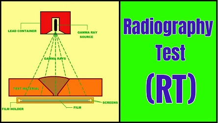
Radiography Test (RT)
Radiography testing (RT) is one of the most widely used non-destructive test (NDT) methods. With the help of this method, we can detect hidden flaws or discontinuities present in welds such as cracks, porosity & blowholes, slag, flux or oxide inclusions, lack of fusion, incomplete penetration, Mismatch, and tungsten inclusion, etc.
Short wavelength electromagnetic radiations such as X-rays or Gamma (γ) rays are used for Radiography testing. Both X-rays and Gamma rays have very high intensity and hence they are able to penetrate the material of any thickness. This high penetrating power is used during radiography testing.
The part to be inspected (Test material) is placed between the radiation source and a sensitive film. If the material is sound or flawless, entire rays (either X-rays or Gamma rays) pass through the material very evenly. But if the material contains any flaw (or flaws), then some of the rays which will pass through the flaws will get absorbed to some extent due to the change in the density. Please note that those rays which will not encounter any flaw will remain intact and will pass through the material evenly. These rays are finally made to fall on a light-sensitive film placed on the backside of the material being inspected.
The material (being inspected) and the sensitive film are kept under exposure to radiation (either X-rays or Gamma rays) for a certain period of time then the film is developed. Once the film is developed, it is called a radiograph.
The density of the film or the amount of darkness on the film will vary depending upon the amount of radiation reaching the film. The darker area on a radiograph indicates more exposure (higher radiation intensity) as compared to the lighter areas which receive less exposure. This variation in the image darkness reveals the presence of flaws or discontinuity inside the film. This variation in the darkness may also be used to determine the thickness or composition of the test material.
Please note that most of the defects possess lesser density than the sound parent metal, hence they transmit radiation (either X-rays or Gamma rays) much better than the sound metal does. Hence the film appears to be darker at the area exposed by the defects.
As explained earlier that both X-rays and Gamma rays are electromagnetic radiation having short wavelengths but very high intensity, now we will learn the steps to be followed for performing the Radiography Test.
Radiography by using X-rays:
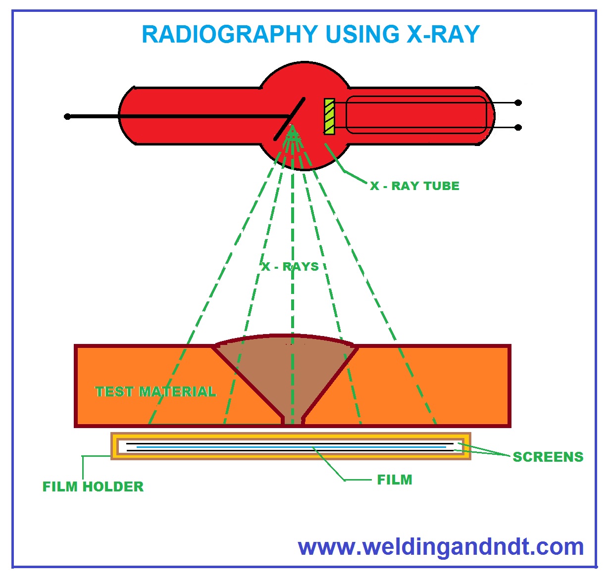
X-rays are produced by an X-ray tube, which is an evacuated tube (usually made of glass) and it contains an electrically heated filament and a tungsten anode. The electrically heated filament releases electrons which are made to hit on the tungsten anode. Due to the collision of high-velocity electrons with the tungsten anode, X-rays are emitted.
These X-rays are allowed to pass through the test material. A cassette containing film is placed behind the test material (part to be inspected). A penetrameter (or Image Quality Indicator IQI) is placed on the side of the source adjacent to the weld.
After the prescribed time of exposure, the source is turned off and the film is sent for development in the darkroom (A darkroom is a place where the film is developed. Click here to learn how the film is developed in the darkroom). After development, the film is inspected with the help of a viewer.
Radiography by using Gamma-rays:
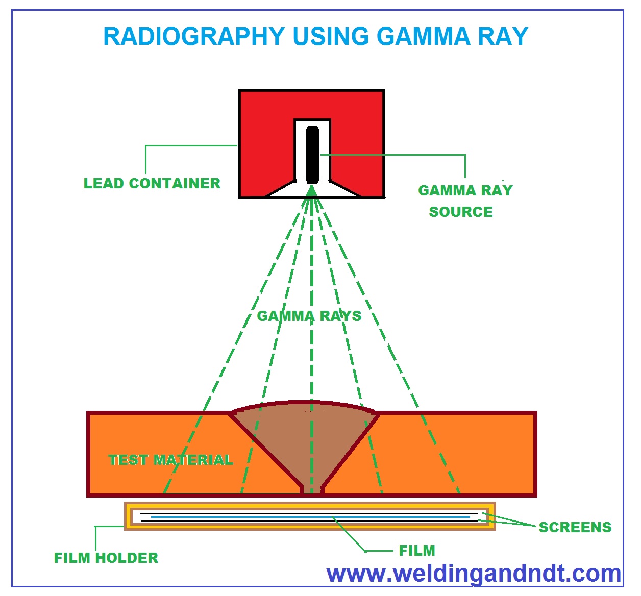
Gamma rays are produced by radioactive isotopes. The nucleus of a radioactive isotope remains unstable. Commonly used isotopes for industrial radiography are:
- Cobalt 60 (Co 60): Half-life of 5.3 years
- Iridium 192 (Ir192): Half-life of 72 days
- Caesium-137 (Cs137) : Half-life of 30 years
A lead or tungsten alloy container of sufficient thickness is used containing the gamma-ray source (300 mg). Such containers are used to provide the necessary protection. These Gamma rays are allowed to pass through the test material. A cassette containing film is placed behind the test material (part to be inspected). A penetrameter (or Image Quality Indicator IQI) is placed on the side of the source adjacent to the weld. The rest of the procedures is the same as the X-ray technique.
Radiography Test Video (Part 1);
Radiography Test Video (Part 2);
Radiography Test Video (Part 3);
Radiography Test Video (Part 4);

Can u also describe about the problems which we will face in the site where we come to know about those on experience……. With ur experience I want to let know what doubts made ur job more difficult in the site…. And please explain even about the ‘T’ joint and Butt joint as well……recently we completed ASNT level-2…..and now we are working on RT……ur little information is also very useful for us…..so pls give an answer…..we will be waiting………….
What are the of 7018 electrod 1 of a tigwelder im working of shipchem but a subcon company
What are the meaning of 7018 electrod im the 1 of tigwelder im working of korean company .
Dear Mr Rex Bince
To understand the meaning of E 7018 Please visit: http://www.weldingandndt.com/welding/welding-electrodes-understanding-the-electrode-symbols/
You can also watch this video for more information on welding electrodes: https://youtu.be/kQ5IcU6VDO8
Thankyou
very informative article and thanks for publishing
Thank you Sir
Sir I have questions regarding penetrameter selection, how much penetrameter is Required for 6 mm, 10 mm, 12 mm, As Per Set A and Set B, how we can go Up side or Downside?
Is grinding allowed during welder qualification test?
Can you about Welding Procedure Specification (WPS)
how to make WPS of any welding process
Very soon, I will upload step by step procedure for preparing WPS for any welding process
Did you tend to use X-Ray or Gamma-Ray more in the field? What are the advantages/disadvantages of using one over the other in fieldwork.
Very informative article thanks for publishing, please provide us with the same article for radiation safety during radiography testing.
Regards
Sir , you have explained very well. please describe also the radiographic technical process like SWSI, DWSI, DWDI , elliptical position, panoramic shot and selection of IQI please describe in brief.
I am very interested in your continaul education programme.
I am a level 2 ASME certified inspector in the five basic NDT courses and I have been working for the pass 6 years. I wish to do a level III course with RT as major.
With BSc. And a welding diploma.
Do You have any advise for me.
Thanka
Dear sir ,
Please make one video on it how it performs actually.
RT not useful for cracks
What is the principle of RT?
Useful for cracks, but not sure for lack od fusion
Plz…sir SFD Formula send details example
sir please mention your youtube channel
rt principles are really important
I can’t wait hooking up to your unbeatable and educative site. kindly do us favour!.
can you relay to us some international career hiring contacts.cheers!!!
Sir,
Kindly explain about
Geometrical Unsharpness (Ug) in detail
SFD Formula
Selection of IQI
Hel sir…
We need about IQI ,and how can use it in RT and what purpose
Tq sir
Sir please sed this videos and some pictures
can we do Radiography test for T joint butt weld ?
What is principles of pt, ut, rt, mt
Weld overlay Pressure vessel is required RT,UT before PWHT and UT after PWHT
in this case, Shall we have to perform RT after weld overlay? Is it required according to ASME CODE?
We wan to perform RT before weld overlay, UT after weld overlay, pwht.