Summary of ASME BPVC Section VIII Div 1 (Part 4)
In Part-3 of this article the Subsection A was covered from UG-36 up to UG-79, to read the Part-3 of this article please click here.
- To read Part-1 of this article, please click here.
- To read Part-2 of this article, please click here.
This article i.e. Part-4 will deal with the general requirements preceding from UG-80 onwards.
Subsection A
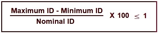
UG- 80: Ovality tolerances for cylindrical, conical and spherical pressure part shells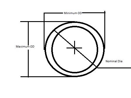 For internal pressure the following formula shall be used:
- External pressure shall meet the requirements as mentioned above for internal pressure and
- Must meet the requirements of figure UG-80.1. For more details, Please refer code.
(Please note that the design calculation won’t be dealt in detail, and the readers are advised to refer the code for their specific type of vessel design.)
UG- 81: FORMED HEAD TOLERANCES
Inner surface out of acceptance (specified shape) is 1.25% of D for tori spherical, tori conical, hemispherical or elliptical head and for acceptance inside the specified shape is 0.625% of D (Nominal inside Dia of pressure equipment). For more details, Pleasse refer code.
UG- 82: LUNGS AND FITTING ATTACHMENTS
All the internal and external attachment on the pressure equipment shall be so built-in so as to conform to the curvature of the shell or head to which they are attached.
When a pressure parts (such as nozzle) and non-pressure parts (ex lugs) which are directly over another pressure part (Shell/head circ or long seam) then the pressure part (nozzle/lugs) seams shall be ground flush.
For others openings, Please refer code.
UG-83: HOLES FOR SCREW STAYS
For details, Please refer code.
UG-84: CHARPY IMPACT TESTS
- This test is performed to check the brittleness (of a normally ductile material) tendency of material at low temperatures.
- They are performed for the weldment (Weld & HAZ) and for the parent material.
- The procedure followed is generally as mentioned in SA 370 (ASME SEC II Part A).
- Suppose the Minimum Design Metal Temperature (MDMT) of the pressure equipment is
- -10°C so in no case the impact test temperature be -9°C but it can be less than -10°C (Say for example -11°C).
- 3 samples shall constitute a set and as far as practicable the size of the specimen shall be 10x10x55 (mm) for plates of 11 mm thick or more and if thickness is less than 11 mm refer code for the specific dimensions and reduction in test temperature with a corresponding reduction in impact absorbed energy values from SA 370.
- Impact test are not required if the max width along the notch of the specimen is less than 2.5 mm.
 Charpy V Notch 2 mm Impact test specimen size: 55(L) x 10(W) x 10(H)
- For detailed dimensions refer code the above figure is for general understanding only.
- Retest: Say for example the average value required is 27 J and the single value permissible for single specimen is 20 J so a retest ( additional set) is required under following conditions:
- Say the values is 22 J, 26 J and 40 J so the average is 29.3 J so two values are below the average hence a set shall be retested from the remaining test coupon with all the conditions same as for the original test.
- Say the values are 19 J, 30 J and 40 J so the average workout to be 29.6 J in which only one value is below single specimen minimum of 20 J and hence a set shall be retested from the remaining test coupon with all the conditions same as for the original test.
- For above two conditions each and every retested sample from the set shall have absorbed impact energy equal to or greater than 27 J.
- A separate article will cover the detailed impact test location (with sketch for each case such as single process, multiple process and different group no) for procedure qualification test coupon along with production test coupon.
UG-85: HEAT TREATMENT
If the heat treatment as per material specification (ex. plate) are not accomplished by the mill than the same may be accomplished under the control of the manufacturer (of pressure equipment) and shall be documented as mentioned in the code.
INSPECTION & TESTS
UG-90: General
- The pressure equipment’s which require U or UM designator shall conform to the general rules of inspection and tests in addition to the necessities of subsection B & C of this code.
- The manufacturer holding U or UM designator certification has the following responsibilities to fulfill the requirements:
- Certification authorized by ASME.
- The design calculations for pressure equipment and its parts along with obtaining of partial data reports.
- Material used in construction of pressure equipment shall be duly recognized.
- Examination (say Combination of UT, RT & LPT) to ascertain the thickness and to detect any defects and maintain traceability.
- Documentation for the test carried out (ex: impact prod test).
- Access for inspection to the inspector, prior approval of base metal repair procedures.
- Availability of WPS, PQR, WPQ, WOPQ, QAP, ITP, and inspection test reports (set up, dimensional etc…) to the inspector and so on and so forth.
- Please refer code for other details.
UG-91: THE INSPECTOR
- In this code inspector will always means an authorized inspector (abbreviated as AI) and will be employed by ASME Recognized agency like Lloyd’s, TUV, HSB etc…
- Inspectors may be employed by the employer (Pressure equipment manufacturer) if the pressure equipment’s manufactured by the manufacturer is for his own use only, otherwise inspectors (AI) shall not be employed by pressure equipment manufacturer.
- Inspector shall also monitor quality management system of the manufacturer.
UG-92: ACCESS FOR INSPECTION
- Without any hindrance the inspector shall be given access to the pressure equipment by the manufacturer weather at site or shop.
- Inspector shall be notified of the progress of the pressure equipment and for any inspection shall be informed by the manufacturer well in advance.
UG-93: INSPECTION OF MATERIALS
- Material Test Reports (MTR) from material manufacture shall be available for evaluation to inspector.
- It shall (MTR) shall document all the tests as required by the material specification and if some of the test are to be made latter proper documentation of the same to be kept.
- For more details refer code.
UG-94: MARKING ON MATERIALS
- Inspector to check the marking on the parts of pressure equipment’s
UG-95: EXAMINATION OF SURFACES DURING FABRICATION
- To guarantee the material is free of any unwanted discontinuity and defects the examination of the surfaces shall be made.
UG-96: DIMENSIONAL CHECK OF COMPONENTS PARTS
- Manufacturer shall conform that the parts of pressure equipment’s conform to the shape (within tolerances) and the thickness of the components after forming.
- Fitness with vessel curvature needs to be determined by the manufacturers for various attachments (Such as Nozzles etc…)
- The Dimensional conformance to the code shall be determined by the inspector.
UG-97: INSPECTION DURING FABRICATION
- Before making a closing seam in the job a complete inspection of the pressure equipment shall be performed.
- Before hydrostatic or pneumatic test inspector shall inspect the external surfaces of the pressure equipment’s.
UG-98: MAXIMUM ALLOWABLE WORKING PRESSURE
- Please Refer code for details
UG-99: STANDARD HYDROSTATIC TEST
Hydrostatic pressure = 1.3 * maximum allowable working pressure (MAWP)
- Please refer code for details
(To learn more about Hydrotest, Please click here.)
UG-100: PNEUMATIC TEST
- Pneumatic test can be used instead of hydrostatic test when the design of the pressure equipment make it unsafe to fill it with water, the pressure equipment cannot be dried easily.
- Pneumatic test pressure = 1.1* maximum allowable working pressure* lowest stress ratio
- Where Stress Ratio = Stress value at test temperature/Stress value at design temperature
- To minimize the risk of inelastic fracture the temperature during the test shall be equal to or greater than 17°C above the minimum design metal temperature.
- The increment in pressure shall be as mentioned in the code.
- For rest of the details refer code.
UG-101: PROOF TESTS TO ESTABLISH MAXIMUM ALLOWABLE WORKING PRESSURE
For details refer the code.
UG-102: TEST GAUGES
For details refer the code.
UG-103: NON DESTRUCTIVE EXAMINATION
Magnetic Particle Inspection and Liquid Penetrant testing where ever referenced shall be performed as per ASME SEC V.
MARKING AND REPORTS
UG-115-116: GENERAL, REQUIRED MARKING
Refer code for details
UG-117: CERTIFICATE OF AUTHORIZATION AND CERTIFICATION MARKS
Refer code for details
UG-118: METHODS OF MARKING
- By utilizing name plate, stamping on to the pressure equipment, electrochemically etched.
- For more details refer code.
UG-119: NAME PLATES
Refer code for details
UG-120: DATA REPORTS
Refer code for details
OVER PRESSURE PROTECTION
- UG-125: GENERAL
- UG-126: PRESSURE RELIEF VALVES
- UG-127: NON RECLOSING PRESSURE RELIEF DEVICES
- UG-128: LIQUID PRESSURE RELIEF VALVES
- UG-129: MARKING
- UG-130: CERTIFICATION MARK
- UG-131: CERTIFICATION OF CAPACITY OF PRESSURE RELIEF DEVICES
- UG-132: CERTIFICATION OF CAPACITY OF PRESSURE RELIEF VALVES IN COMBINATION WITH NOR RECLOSING PRESSURE RELIEF DEVICES
- UG-133: DETERMINATION OF PRESSURE- RELIEVING REQUIREMENTS
- UG-134: PRESSURE SETTING AND PERFORMANCE REQUIREMENTS
- UG-135: INSTALLATION
- UG-136: MINIMUM REQUIREMENTS FOR PRESSURE RELIEF VALVES
- UG-137: MINIMUM REQUIREMENTS FOR RUPTURE DISK DEVICES
- UG-138: MINIMUM REQUIREMENTS FOR PIN DEVICES
- UG-140: OVER PRESSURE PROTECTION BY SYSTEM DESIGN
- Refer code for Details
(Note: Purpose of this article is to give a general guideline to the readers and it shall not be considered as a substitute of code. For full terms and conditions please read ASME Section VIII DIV I, 2017 edition).
This article is written and published by;
MR. SANDEEP SINGH PARMAR
(Ex. GE, ISGEC & ESSAR)
Email: sandeepparmar99@yahoo.com
IWE (IN/IWE/41700026); B Tech (Mechanical); AMIIW (Welding Technology)
ISO 9001:2008 Internal Auditor; ISO 9001:2015 Lead Auditor ;
NDE L-II (UT, LPT, MPI, RT); Lean Six Sigma Green Belt;
MWeldl IEng; MIE C Eng(Ind) ; M.I.Inst.W ; LM IIM