Knuckle Joints
WHAT IS A KNUCKLE JOINT?
A knuckle joint is a type of mechanical joint used to join two components that are loaded under tensile load. One has a fork with holes on either side, forming a double eye, while the other component has a Single eye. The single eye is inserted between double eyes so that all three holes are centered, and a pin is used to secure these components. These joints are used for different types of connections e.g. tie rods, tension links in bridge structure roof tiles, bridges, and cranes, etc. These joints can easily be assembled and dissatisfied. The ability to allow some rotations can be advantageous in truss structures because it ensures that the structural members remain under a net stress load and are not subject to bending moments, which can increase the stress. Now let’s discuss this more clearly;
- Knuckle joints always have a fork end, an eye end, & a pin. Usually, these are all specially made parts, though the standard rod ends are sometimes used for the ends of the eye.
- This has the advantage that an end rod performs an additional rotation motion perpendicular to the axis, protecting against bending constraints.
- The axle can be bolted in case of huge structural materials like bridges, heavy-duty vehicles, etc.
- A single degree of freedom (1-DOF) kinematics pair is allowed in this joint so this joint is also called as an inverted joint or pin joint allowing only relatives rotation about the single axis. The other two degrees of freedom are seized in it.
- This is a type of joint that connects two cylindrical rods whose axes lie on the same plane and under tensile loads. It is used to transmit axial tensile force. This joint allows the angular movement of two cylindrical rods in one plane.
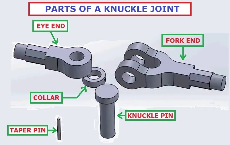
PARTS OF A KNUCKLE JOINT:
- Eye part
- Double Eye End or Fork End.
- Two rods are to be connected
- Knuckle Pin.
- Collar.
- Tapers Pin or Lock Pin
Different parts of a knuckle joint shown in the below figure;
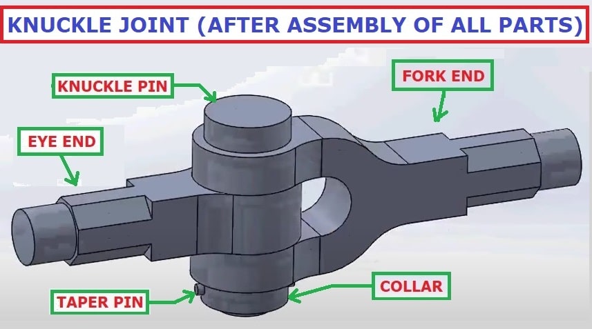
The Assembly of different parts of a knuckle joint is shown in the below figure;
CONSTRUCTION AND FUNCTIONS OF DIFFERENT PARTS:
The arrangement as shown in the above figures has an eye fork end & one eye end. The collar, taper pin & Knuckle pin provides an axial arrangement to these joints. The end of one eye is placed between two eye ends or two eyes of a fork. After that, a nozzle pin is inserted at the end of the eye and the end of the fork. The fork pin is used to hold the fork end and eye end together.
Some part of the knuckle pin comes outside of the lowermost hole of the fork end.
There is a small hole under the knuckle pin, at the ends of the eye, and fork Collar and tamper pins are used to lock the knock pins.
The collar is placed in such a way that the holes of the knuckles are attached to the collar hole, and a taper pin is inserted from the collar hole into the collar hole having two pinholes.
This simplifies the formation of the Knuckle joint, some parts of the knuckle pin comes outside of the lowermost hole of the fork end.
FAILURE OF DIFFERENT PARTS IN A KNUCKLE JOINT:
Types of failures that can occur in knuckle joints are;
1. Tensile failure of Flat Ends
2. Tensile failure of Solid Rod
3. Failure of Single Eye End & Shears Pin Hole
4. Pin crushed against the rod
5. Shear failure of Knuckle Pin
6. Tensile failure of Double Eye End
DESIGN OF KNUCKLE JOINT:
Material selection: The material selected is low carbon steel, which can withstand the stresses developed in the material, as the joint is subjected to reversible stress, then the induced stress will be repeated, and the joint may fail due to fatigue.C-30 is selected as the material for all parts
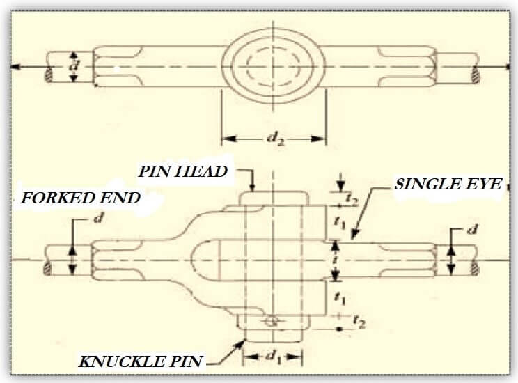
The assembly diagram of the knuckle joint is as shown in the above figure.
The dimensions of knuckle joints are:
- Diameter of rod = d
- Diameter of knuckle pin = dp = d1
- Outside diameter of single eye = doe = d2
- Outside diameter of double eye = dod
- Thickness of single eye = t
- Thickness of fork = t1
- Axial tensile force on rod = P
(1) Diameter of rod
Consider the rod is subjected to a direct tensile stress
ς(Zeta) = P / π d2
From the above equation, the diameter of the rod ‘d’ is obtained.
(2) Design of pin (dp)
(a) Consider the failure of the pin under double shear due to tensile force.
Therefore, direct shear stress induced in knuckle pin is given by Equation
| ς(zeta) = P / 2A = (P/2) / (π/4) dp2 = 2P / π dp2 |
(b) Failure of knuckle pin in bending
Assume there is no clearance or slack but in actuality, knuckle pin is loose in forks to permit angular moment of one with respect to other, so it is subjected to bending moment in addition to shear, consider uniformly distributed load along the portion of the pin.
Taking moment about axis XX
M = [(-P/2) × (t/4)] + { (P/2) × [ (t/2)+(t1/3) ] }
= P/2 [(t1/3)+(t/2)-(t/4) ]
| = P/2 [ (t1/3)+(t/4) ] |
Section modulus,
| Z = (π/ 32)dp3 |
Maximum bending stress, σb
| σb= M/Z = { P/2 [(t1/3)+(t/4)] } / {(π/ 32)dp3} |
Here, we check the pin in bending and find the value of dp
(3) Design of single eye :
(a) To find the outside diameter of single eye (doe) The single eye is subjected to a direct tensile stress, due to this single eye under the tear.
| σt = P/A = P/ (doe-dp)× t |
(b) Due to direct tensile strength, the single eye is subjected to double shear.
Resisting shearing area = 2(doe-dp)×(t/2)
The direct shear stress induced is
| ς(Zeta)=P/(doe-dp)×t |
From this equation, the outside diameter of the single eye doe is obtained.
(C) Failure of single eye or pin due to tensile load in crushing
Resisting crushing area = dp × t
| σc = P/(dp×t) |
From this equation crushing stress checked if fail, increase the thickness of the eye (t).
(4) Design of fork (double eye)
(a) The tearing of the double eye at weakest section due to tension
| Area resisting tear = (dof – dp) × 2 t1 σt = p/ [(dof – dp) × 2 t1] |
From this equation, find the outside diameter of the fork (dof).
(b) Failure of the double eye (fork) in double shear due to tensile load.
| Area resisting shear = 4 × [(dof – dp) ]/2 × t1 = 2 × (dof – dp) t1 The shear stress is given by, ς(zeta) = p/[(dof – dp) × 2 t1] |
From this equation, check shear stress if less than design, increase the thickness of fork t1.
(c) Failure double eye in crushing (thickness of fork)
Double eye may fail in crushing due to tensile load
| The crushing stress is given by, σc = P/( 2×dp ×t1) Check crushing stress or find t1 |
Application of Knuckle Joint:
The following are the main points of knuckle joint applications:-
- Link of roller chains, bicycle chains, and watch chain straps.
- The valve mechanism of a reciprocating engine.
- The fulcrum for the lever.
- Link of roller chains, bicycle chains, and watch chain straps.
- The joint between the tie rod joints of a roof truss.
- In an automobile, a finger wheel is supporting the skeleton for assembly.
- Tie rod joint of the jib crane.
- The knuckle joint is also used in wheel alignment parts of tractors.
- This eccentric flush work on some occasions uses a downward string such as barrel steps, lateral drilling, etc.
- It is also used in robotic arms or earthmovers such as grains or tanks.
- Knuckle joints are mainly used for combining in rail compartments.
- It is used in the vehicle’s windshield wipers.
Advantages of Knuckle Joint:
Followings are the main advantages of knuckle joints:-
- The Knuckle joint withstands high tensile loadings, less expensive, and more reliable.
- Strong mechanical rigidity.
- It can be easily assembled and disintegrated.
- High repetition accuracy even with material thickness and tensile strength & Long tool life.
- This leads to high system rigidity.
Disadvantages of Knuckle Joints:
Followings are the main disadvantages of knuckle joints:-:-
- Unable to withstand large compressive loads.
- It is not as flexible as a universal joint.
- Angular movement is constrained to only one plane.
REFERENCES:
1. R.S. Khurmi, J.K. Gupta. A textbook of machine design. Ram Nagar, New Delhi: Eurasia Publishing House. ISBN 81-219-2537-1 (2008).
2. Analysis of Knuckle Joint of 30C8 Steel for Automobile Application -Sourav Das, Vishvendra Bartaria, Prashant Pandey: International Journal of Engineering Research & Technology (IJERT) Vol. 3 Issue 1, January – 2014
3. Bhandari, V.B. (2001). Introduction to machine design. New Delhi: Tata McGraw-Hill. 2001
4. Material Optimization for Knuckle Joint by Using FEA Somase Anil R1, Dhole Sumit M2, International Research Journal of Engineering and Technology (IRJET) e-ISSN: 2395-0056 Volume: 06 Issue: 10 | Oct 2019 www.irjet.net
5. https://fastenerengineering.com/what-is-a-knuckle-joint/ By Michelle Froese
This article is written by:
MR. ABHISHEK SRIVASTAVA
B.TECH (MECHANICAL ENGG.)
- 4+ Years of Industrial Experience
- 2+ Years of Teaching
E-Mail: abhi.allahabad122@gmail.com