CSWIP 3.1: Leading Multiple Choice Questions with Full Explanations
Q1. Which is the best destructive test for showing lack of sidewall fusion in a 25mm thickness butt weld? Nick break
Read More
Q1. Which is the best destructive test for showing lack of sidewall fusion in a 25mm thickness butt weld? Nick break
Read More
Welding is an essential process in construction and manufacturing, allowing different metal parts to be joined together. One common type
Read More
Q1. What is the primary purpose of using pipe fittings? To connect different sections of piping To increase the speed
Read More
Q1: What is the primary purpose of ASME Section IX, Part QG? To outline the general requirements for welding To outline
Read More
Q1. How does the presence of molybdenum in SS316 affect its corrosion resistance compared to SS304? Increases resistance to pitting
Read More
Q1. What is the primary purpose of a welding procedure specification (WPS)? To outline the qualifications of the welder To
Read More
Q1. Which of the following factors can affect the accuracy of flaw detection in UT? Beam divergence Surface roughness Frequency
Read More
Q1) Which welding process is generally preferred for large-scale, high-production applications due to its high deposition rates and ability to
Read More
Q1. Which of the following welding processes would give the highest heat input when using typical parameters? Tungsten Inert Gas
Read More
Q1. Which welding process utilizes a non consumable electrode? SAW MMA TIG MIG (Explanation: In TIG welding, a tungsten electrode is
Read More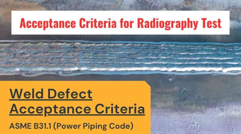
The weld defect acceptance/rejection criteria are given in Chapter VI (Inspection, Examination, and Testing) of the ASME B31.1 – 2022 Power Piping Code. Chapter
Read More
For the complete identity of a material we need two things; Material Specification Material Grade For Example, In SA 106
Read More
ASTM A 36 or SA 36 is basically carbon steel of structural quality which is widely used in industries. It
Read More
The mechanical properties of the metals are those which are associated with the ability of the material to resist mechanical
Read More
WHAT IS A KNUCKLE JOINT? A knuckle joint is a type of mechanical joint used to join two components that
Read More
The commonly used terms and definitions related to valves is given below; Actual pressure drop: The difference between the inlet
Read More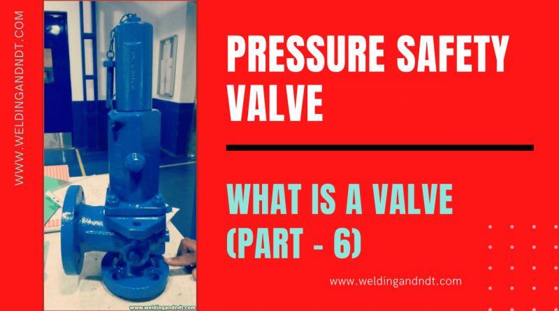
Pressure Safety Valve / Relief Valve A safety valve is a valve that acts as a protection of equipment from
Read More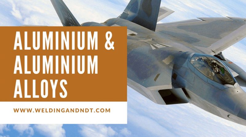
Introduction: Aluminum is found on the earth in its oxidized form known as Bauxite. Bauxite is refined to produce Alumina
Read More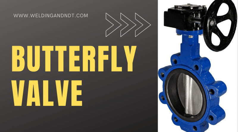
In the Valves Part-1, we discussed what is a valve, its history, and its categorization (Click here to read). In
Read More
In the Valves Part-1, we discussed what is a valve, its history, and its categorization (Click here to read). In
Read More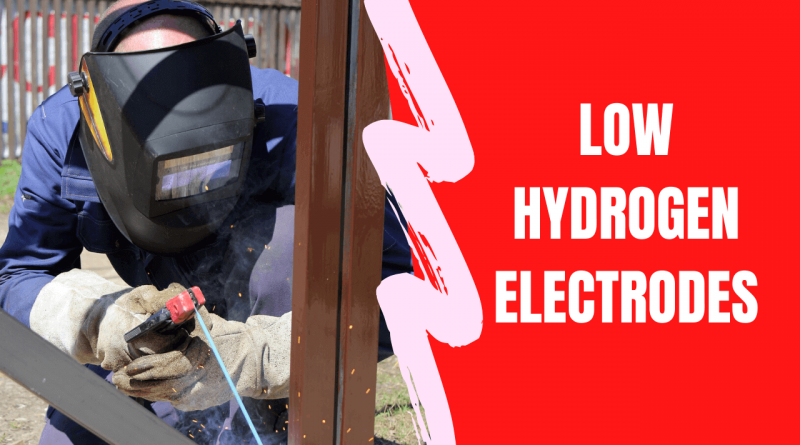
Low Hydrogen electrodes are very popular in the industries because of the following reasons; Ability to produce X-ray quality welds
Read More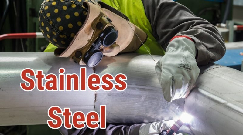
This article covers the following topics/questions; What is stainless steel? Types of stainless steel. Is stainless steel magnetic? Stainless steel
Read More
Underwater welding is used for repairing ships, offshore structures including oil drilling rigs, and pipelines that are submerged in water.
Read More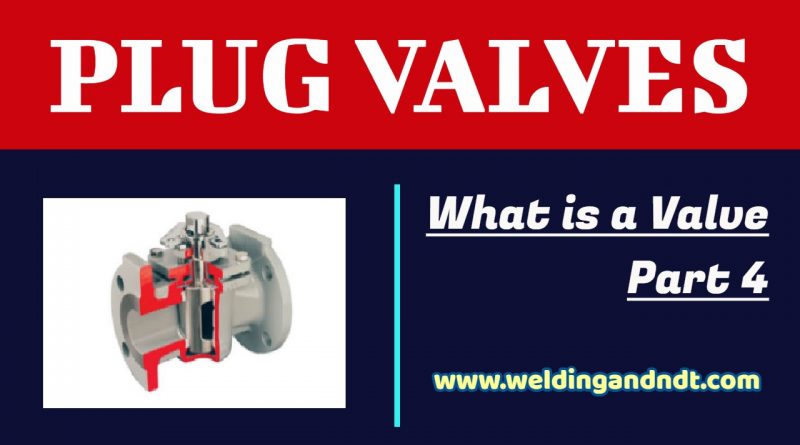
In the Valves Part-1, you learned what is a valve, its history, and its categorization (Click here to read). In
Read More
In the Valves Part-1, you learned What is a valve, its history, and its categorization (Click here to read). In
Read More
Scope: In this article fundamentals of heat treatment will be discussed briefly mainly related to the “base material” of welded
Read More
Scope: In this article, fundamental concepts of heat treatment will be discussed to give an overview to the reader with
Read More