Ball Valves – What is a Valve (Part – 5)
In the Valves Part-1, we discussed what is a valve, its history, and its categorization (Click here to read).
In Part-2, we discussed about Globe valves (Click here to read).
In Part-3, we discussed about Gate valves (Click here to read).
In Part-4, we discussed about Plug valves (Click here to read).
In this part, we will learn about Ball Valves.
Ball Valve:
The ball valve is a quarter-turn operated valve. The closure member is a spherical plug with a through-hole. When the valve is in the open state, the through-hole is in-line with the fluid flow and hence, the fluid passes through it. The valve is closed by rotating the globe by 90 Deg. such that the hole now becomes perpendicular to the flow and hence, stops the flow.
The seat is usually circumferential, made up of soft materials to offer a tight shutoff. The seat can be made either out of plastic or metals. Ball valves are not recommended to be used in a partially open condition. Due to misalignment between the flow direction and opening of the plug, a large pressure drop takes place in the partially open condition.
There are four general body styles of ball valves, Namely;
- Split-body ball valve
- Top-entry ball valve
- End-entry (Side-entry) ball valve
- Three-piece body ball valve
The difference is based on how the pieces of the valve are manufactured and assembled, but the valve operation is the same in each type. Each design has its benefits.
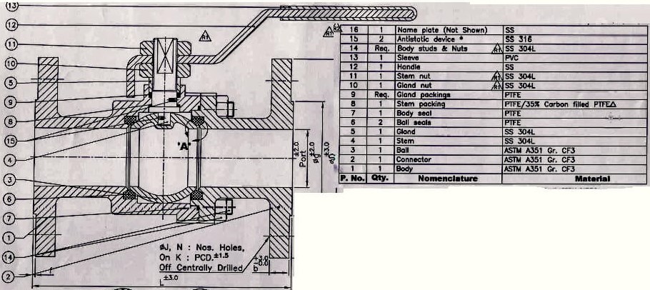
Split-body ball valve (Figure 1) design consists of a two-part body, a cover, ball, seat rings, stem, and other internals. The two-part body is held together by a flange connection. One body part is smaller than the other. The ball is inserted in the larger body part, and the smaller body part is assembled by a bolted connection. The stuffing box is constructed integrally with the larger body part. On smaller size split-body ball valves, the two-part body is joined by a threaded connection. The flanged or threaded joint between the two-part body is an added source of potential leakage.
Figure 1
Top-entry ball valves (Figure 2) allow access to valve internals for assembly, dis-assembly, repair, or maintenance by removal of the valve bonnet-cover. The valve is not required to be removed from the pipeline.
Figure 2
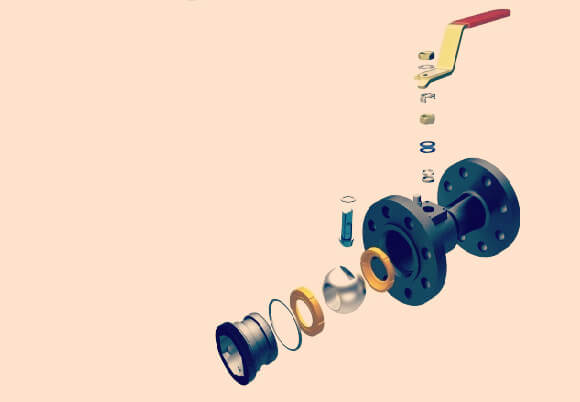
End-entry (Side-Entry) ball valves (Figure 3) have a single-piece body. The ball is inserted from one end and is retained by an insert. These valves have flange- or screwed-end connections. This design is commonly used for inexpensive small valves.
Figure 3
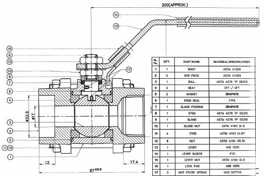
Three-piece body ball valve’s (Figure 4) middle part is the major part that holds all valve internals, and the stem passes through a hole in the top. Two end caps are held together with the middle body by bolts or studs and nuts. The end connections are part of the end caps, and they may be butt-welding, socket welding, threaded, or flanged.
Figure 4
There are three types of ball valves based on ball movement, Namely;
- Trunnion mounted ball valves
- Floating type ball valves
- Rising stem ball valves
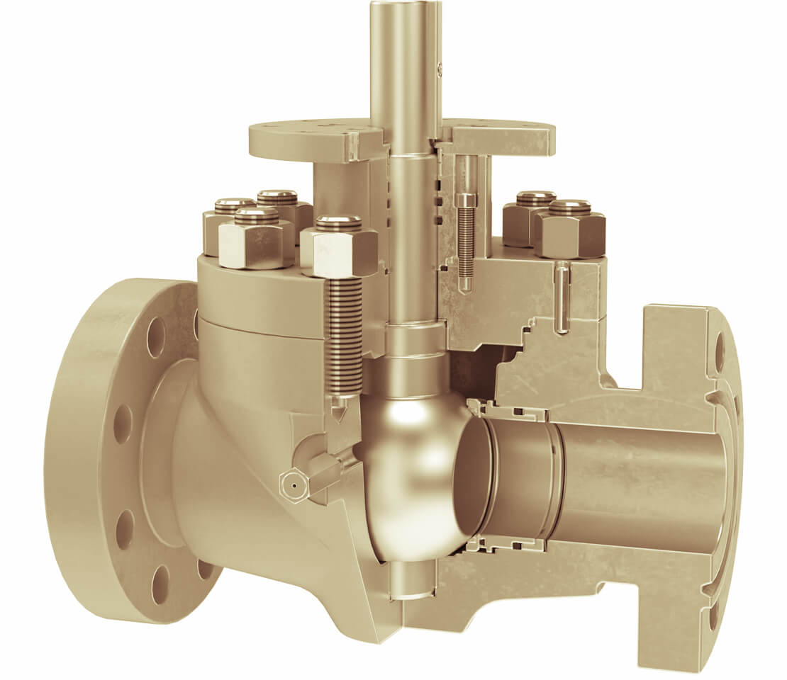
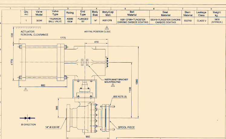
Trunnion mounted ball valve (Figure 5) has additional mechanical anchoring at the top and bottom on the ball. This special mounting is suitable for larger and higher-pressure valves. Moreover, this design allows for a reduction in valve torque as the ball is supported in two places. The trunnion mounted stem absorbs the thrust from the line pressure, preventing excess friction between the ball and seats, so even at full rated working pressure operating torque remains low.
Figure 5
Floating Ball Valve is not held in place by a trunnion, and instead is attached only to the stem. This sometimes causes the ball to float slightly downstream. However, when this happens, the ball presses against the seat, creating a positive seal.
Rising Stem Ball Valve incorporates tilt-and-turn operation, eliminating seal rubbing which is one of the primary causes of valve failure. When the valve is closed, the core is wedged against the seat, ensuring positive shutoff. When the valve is open, the core tilts away from the seal and the flow passes uniformly around the core face. The Rising stem ball valve utilizes this operating principle, delivering fast, low-torque operation and long-term reliable performance. Additionally, the valve can eliminate localized high- velocity flow that typically creates uneven seat wear exhibited by an ordinary ball, gate, and plug valves.
Additionally, there are three basic types of bores for ball valves: Namely Full port, Reduced port (also known as Standard port), and V-port. These four types have different constructions and purposes.
Full-Port Ball Valve (Figure 6) also known as a full-bore ball valve has a bore internal diameter (ID) approximately equal to the pipeline ID. This allows for reduced friction and pressure loss across the valve. With a full-port ball valve, there is no restriction to the flow of fluid, but the valve can be more expensive. This type of bore is ideal for situations where pigging may be necessary. The Cameron TBV series split-body, full-port, flanged ball valve combines its sealing technology and design expertise with the versatility to solve even the most demanding applications. This technology is widely used in the chemical, petrochemical, and refining industries.
Reduced-Port Ball Valve (Figure 6) also known as a reduced-bore ball valve is a valve in which the bore is reduced to one or two nominal sizes lower. This provides a more restricted flow path, generally resulting in higher energy losses. Known for its robust design, superior sealing areas, and stainless-steel overlays, it is widely used for the oil and gas industry’s most severe service applications.
Figure 6

V-Port Ball Valve has either a “v” shaped ball or a “v” shaped seat. This type of valve also is known as a control valve in which the flow velocities need to be controlled as required per the application.
This article is written by
Mr. Goutham Rathinam
(BE-Mechanical & CSWIP 3.1-TWI,UK)
Email ID: goutham.r86@gmail.com