ASME SEC VIII DIV I deals with the rules for the construction of pressure vessels. This code is a part of ASME BPVC Codes (Click here to learn about the various codes published by ASME).
Code Cases are published regularly by the BPVC committee to consider proposed additions and revisions to the code and to formulate cases to clarify the intent of existing requirements when the need is urgent.
These code cases will be incorporated into the preceding editions (Say for example those code cases which are adopted after 2017 edition up to 2019 will be reflected in 2019 edition).
Scope of ASME Section VIII Div. 1
This Code contains compulsory requirements, specific prohibitions, and non-mandatory guidance for pressure vessel materials, design, fabrication, examination, inspection, testing, and certification, and pressure relief.
This code is not a handbook and cannot replace education, experience, and use of engineering judgment. The use of engineering judgment should not be used to overrule the mandatory requirements of this code.
Use of Code:
The Code is published every two years now and becomes mandatory after six months of its publication (For example ASME SEC VIII DIV I published on July 1 2017 becomes mandatory from Jan 1, 2018).
The Body of ASME SEC VIII DIV I:
Subsection A: General Requirements
- Part UG: General Requirements for All Methods of Construction and All Materials
Subsection B: Requirements pertaining to the Methods of Fabrication of Pressure Vessels
- Part UW: Requirements for Pressure Vessels Fabricated by Welding
- Part UF: Requirements for Pressure Vessels Fabricated by Forging
- Part UB: Requirements for Pressure Vessels Fabricated by Brazing
Subsection C: Requirements Pertaining to the Classes of Materials
- Part UCS: Requirements of Pressure Vessels Constructed of Carbon and Low alloy Steel
- Part UNF: Requirements of Pressure Vessels Constructed of Non Ferrous Materials
- Part UHA: Requirements of Pressure Vessels Constructed of High Alloy Steel
- Part UCI : Requirements of Pressure Vessels Constructed of Cast Iron
- Part UCL: Requirements for Welded Pressure Vessels Constructed of Material with Corrosion Resistance Integral Cladding, Weld Metal Overlay Cladding, or Applied Linings
- Part UCD: Requirements of Pressure Vessels of Cast Ductile Iron
- Part UHT: Requirements of Pressure Vessels of Ferritic Steels with Tensile Properties Enhanced by Heat Treatment
- Part ULW: Requirements of Pressure Vessels Fabricated by Layered Construction
- Part ULT: Alternate rules for Pressure Vessels Constructed of Materials having Higher Allowable Stresses at Low Temperature.
- Part UHX: Rules for Shell and Tube Heat Exchangers
- Part UIG: Requirements of Pressure Vessels Constructed of Impregnated Graphite
- Part UCD: Requirements of Pressure Vessels of Cast Ductile Iron
Mandatory Appendix
Non Mandatory Appendix
Figures, Tables & Forms
Figure 1: A snapshot of ready to Dispatch Pressure Vessel
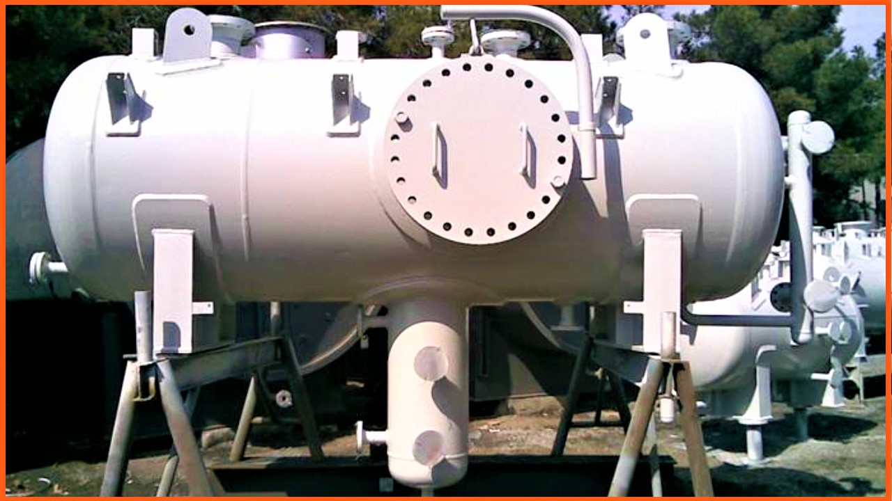
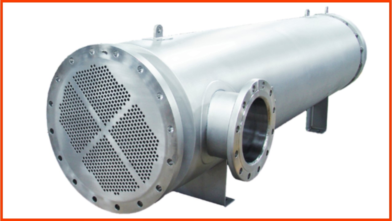
Figure 2: A snapshot of ready to Dispatch Pressure Vessel (Shell and Tube Type Heat Exchangers)
Note: In this part of the article we will cover Subsection A (with focus on welding)
Subsection A
UG 1: SCOPE
The requirements in this section apply to all pressure vessels and vessel parts and shall be used jointly with the specific requirements as given in Sub Section B, C, and Mandatory Appendices.
UG 4: MATERIALS
Materials for Pressure Parts Shall conform to the requirements given in ASME SEC II Part D, subpart 1. Table 1A, 1B, and 3 including all the applicable notes. Materials can be Dual Certified (For Example a plate can be certified as SA 516 Gr 60 and SA 516 Gr 70 as per ASME SEC II PART A by mill provided the material meets all the requirements of the identified material specification or grades.
Non Pressure parts (Lugs, Skirts, etc…) need not be identified but in a case attached by welding shall be of weldable quality.
Materials other than those allowed by the rules of this division shall not be used.
Engineering judgment to be used by the manufacturer to assure the user that the materials used for the construction of pressure vessels will perform satisfactorily for the intended service. Refer informative guidance regarding the metallurgical phenomenon in ASME SEC II part D non mandatory appendix A.
The material physical properties required by design shall be taken from ASME SEC II Part D subpart 2. If the Code does not contain the properties values the manufacturer may use other authoritative sources for the needed information. The manufacturer MDR in the remarks shall mention the source of the information.
UG-5-6-7-8: BASE MATERIALS
The Plate, Forgings, Castings, Pipe, and Tubes used in the construction of pressure vessels for pressure parts shall conform to the requirements of specific clauses except as otherwise permitted.
UG-9: WELDING MATERIALS
The welding material must comply with the requirements of this code, ASME SEC IX, Qualified WPS, and ASME SEC II Part C
UG-10: MATERIALS IDENTIFIED WITH OR PRODUCED TO A SPECIFICATION NOT PERMITTED BY THIS DIVISION, AND MATERIAL NOT FULLY IDENTIFIED
- Any unspecified material (single production lot) for the construction of vessel may be accepted provided the following conditions are met:
- Recertification shall be vessel and part manufacturer only.
- The documentation shall be available to show to the part or vessel manufacturer that all the requirements of this code are met. Material marking acceptable to the inspector.
- If any material with the specification which is not permitted by ASME Section VIII Div. 1 but belongs to a particular production lot as per the requirements of a specification permitted by this division, but which cannot be qualified in above condition shall meet the following conditions to be acceptable:
- Recertification shall be by the vessel and part manufacturer only.
- When documentation demonstrating complete conformance to the chemical requirements is not available, chemical analyses are made on different pieces from the lot to establish a meaningful analysis that is to be accepted as representative of the lot. The chemical analysis shall conform to the specifications.
- Those mechanical properties which are not reported shall be tested and should conform to the specification.
- The material if not heat treated as per specification shall be heat treated either before or during fabrication.
- All other applicable requirements (including, but not limited to, melting method, melting practice, deoxidation, chemical analysis, mechanical properties, grain size, and quality) of the specification permitted by this Division, to which the material is to be recertified, have been demonstrated to have been met.
- The material marking shall be acceptable to the inspector and the material shall be marked as required by the specifications.
- Material not fully identified: Won’t discuss this part in detail as it would be recommended to avoid such material in pressure vessels.
UG-11: PRESSURE PARTS (PREFABRICATED OR PREFORMED) FURNISHED WITHOUT A CERTIFICATION MARK
- The pressure parts (Prefabricated or preformed) to be used for pressure vessels, which are subject to stresses due to pressure and have been furnished by others or by the manufacturer (of the completed vessel) shall conform to all applicable requirements of this Division.
- Parts that are prefabricated (Preformed) may be supplied as follows :
- Cast, forged, rolled, or die formed non-standard pressure parts: Pressure parts like shells, heads, etc. that are entirely formed by casting (ex: Shell), forging (ex: Nozzle, Shell), rolling (ex: Rolled Shell), or die forming (ex: Head) that do not require shop inspection may be supplied basically as materials.
- Cast (ex: Shell), forged (ex: Nozzle), rolled, or die formed (ex: Head) standard pressure parts that comply with an ASME product standard (ASME SEC II PART-A-B), either welded or seamless.
- Cast, Forged, Rolled, or Die Formed Standard Pressure Parts that comply with a standard other than an ASME product standard (ANSI Standard), either welded or seamless.
- The Code recognizes that manufacture (ASME Certificate Holder) may fabricate parts in accordance with UG-11(d), and that is marked in accordance with UG-11(d)(8).
Instead of the requirement in UG-11(d)(4)(-a), the manufacturer may subcontract to an individual or organization not holding an ASME Certificate standard pressure parts that are fabricated to a standard other than an ASME product standard.
UG-12-13-14: BOLTS & STUDS, WASHER & NUTS, RODS & BARS
- UG-23, UCS-11 & UNF-13, Subsection-C to be followed for acceptance respectively
UG-15 PRODUCT SPECIFICATION
- For a wrought (Forged, Rolled, Extruded, etc.…) product when there is no particular specification listed in subsection C, but there is an approved specification listed in subsection C of some other wrought product of that grade the product for which there is no specification can be provided
- The chemical and physical properties, heat treating requirements, and requirements for deoxidation, or grain size requirements conform to the approved specification listed in Subsection C.
- The manufacturing procedures, tolerances, tests, and markings are in accordance with a Section II specification covering the same product form (Forged, Rolled, Extruded etc…) of similar material.
- For the case of welded tubing made of plate, sheet, or strip, without the addition of filler metal, the appropriate stress values are reduced by 15%.
- The product is not pipe or tubing fabricated by fusion welding with the addition of filler metal unless it is fabricated following the rules of this Division as a pressure part.
- Mill test reports reference the specifications used in producing the material and also refer to this paragraph.
- Example Alloy 316L is available as a plate and is listed under SA 240. It can be used as bar or pipe materials under SA-479 and SA-312, even though it is not listed under these specifications. The material must meet the chemical and physical requirements of SA 240 and the product and quality requirements of the applicable product specification).
UG-16 DESIGN
- The design of pressure equipment and its parts shall conform to the requirements in the following paragraphs and in addition to the specific requirements given in the applicable Parts of Subsections B and C.
- Minimum thickness of pressure retaining components shall be 1.5 mm excluding corrosion allowance except that the above does not apply to heat transfer plates, inner pipe of double pipe heat exchangers for NPS 6(150), or less.
- The minimum thickness of shells and heads of unfired steam boilers shall be 6 mm exclusive of any corrosion allowance.
- The minimum thickness of shells and heads used in compressed air service, steam service, and water service, shall be 2.5 mm exclusive of any corrosion allowance.
- This minimum thickness does not apply to the tubes in air-cooled and cooling tower heat exchangers if all the following provisions are met:
- The tubes shall not be used for lethal UW-2(a) service applications.
- The tubes shall be protected by fins or other mechanical means.
- The tube outside diameter shall be a minimum of 10 mm and a maximum of 38 mm.
- The minimum thickness used shall not be less than that calculated by the formulas given in UG-27 or 1-1 and no case less than 0.5 mm.
The Plate Under Tolerance:
- Plate material shall not be ordered with a nominal thickness thinner than the design thickness.
- Plate material with an actual thickness less than the design thickness shall not be used unless the difference in thicknesses is less than the smaller of 0.3 mm or 6% of the design thickness.
- If plate material is ordered to a specification that allows an under tolerance greater than the smaller of 0.3 mm or 6% of the nominal thickness, the thickness of the plate ordered shall be increased, if required, so that the plate material will meet the requirement of (1.5 mm) when used.
The Pipe Under Tolerance:
- Pipe and tube material may be ordered by its nominal wall thickness. However, manufacturing under tolerance must be taken into account when designing or ordering the component.
- The under tolerance need not be considered when designing nozzle wall reinforcement.
- Corrosion Allowance Used in Design Formulas: It is included in every dimensional formula used in this code.
- Examples showing the application of the design rules of this Division are contained in ASME PTB-4, ASME Section VIII, Division 1, and Example Problem Manual.
Please click here to read the next part of this article.
(Note: The purpose of this article is to give a general guideline to the readers and it shall not be considered as a substitute of code. For full terms and conditions please read ASME Section VIII DIV I).
This article is written and published by;
MR. SANDEEP SINGH PARMAR
(Ex. GE, ISGEC & ESSAR)
Email: sandeepparmar99@yahoo.com
IWE (IN/IWE/41700026); B Tech (Mechanical); AMIIW (Welding Technology)
ISO 9001:2008 Internal Auditor; ISO 9001:2015 Lead Auditor ;
NDE L-II (UT, LPT, MPI, RT); Lean Six Sigma Green Belt;
MWeldl IEng; MIE C Eng(Ind) ; M.I.Inst.W ; LM IIM
Really these articles are most valuables for construction of BPVC & I appreciates you sir for your hard & smart work that you have represented all these articles in very simple way of understanding ….