Summary of ASME BPVC Section VIII Div 1 (Part 2)
In Part-1 of this article we had discussed about what ASME SEC VIII DIV I deals, code cases, scope, its use and body of the code. The Subsection A was covered up to UG-16 (Design) and to read the Part-1 of this article please click here.
This article i.e part – 2 will deal with the general requirements preceding from UG-17 onwards.
Please note that the design calculations won’t be dealt in detail, and the readers are advised to refer the code for their specific type of vessel design.
Subsection A (UG – 17 onwards)
UG- 17: METHODS OF FABRICATION IN COMBINATION
A Combination of fabrication methods can be used for design and fabrication of pressure equipment’s as per this code.
UG- 18: MATERIALS IN COMBINATION
Any combination of material as mentioned in Subsection C of this code can be utilized in construction of a vessel and joining of dissimilar joints requirements of ASME SEC IX shall be met.
The rules of the code shall govern the necessities for the parent metal its heat affected zone (HAZ) and weld metal(s) in case the parent metals of different metallurgies needs to be joined together.
Say, for example when SA 516 Gr 70 (Carbon Steel) is welded directly to SA 240 TP 316L (Austenitic Stainless Steel) using E Ni Cr Fe-3 (SMAW Process) as filler metal the applicable rules of this division shall apply to each of the following separately:
- CS parent metal & HAZ
- ASS parent metal & HAZ
- Ni Filler Metal
UG- 19: SPECIAL CONSTRUCTION
Combination units: won’t discuss this further (types are mentioned below).
- Common Element Design
- Differential Pressure Design
- Mean Metal Temperature Design
- Special Shapes
- When no design rules are given the max allowable working pressure of the completed vessel shall be established in accordance with provisions of UG-101.
UG- 20: DESIGN TEMPERATURE
Maximum temperature: For the parts under consideration maximum temperature shall be greater than the average metal temperature through thickness of the vessel expected in service except for lethal service. It can be derived by measurement from a similar equipment in service. (Refer WRC Bulletin 470, “Recommendations for Design of Vessels for Elevated Temperature Service” has information that may prove helpful to the vessel designer).
Minimum temperature: It shall be the lowest expected temperature experienced by the pressure equipment in service and accordingly the plate, casting, forgings, fittings etc shall be selected for construction.
Designer shall keep in mind the lowest operating temperature in service, the surrounding temperature, the effects of immediate startup and shut down etc. while designing the pressure equipment.
Methods of obtaining the service temperature is also mentioned in the non-mandatory appendix of this code.
As there is greater risk of brittle failure for carbon and low alloy steel so following requirements to be met for impact test exemptions:
(1) For P-No. 1, Gr. No. 1(SA 516 Gr 60) or 2 (SA 516 Gr 70), can only be used if the requirements of (a) and (b) below are met:
(a) Curve A material max thickness restricted to 13 mm
(b) Curve B, C and D materials thickness restricted to 25 mm.
(2) The complete pressure equipment to be either hydrostatically or pneumatically tested with the provisions of this code.
(3) Designer shall ensure the temperature range is between 345°C and -29°C. However irregular temperature below -29°C may be allowed.
UG-21: DESIGN PRESSURE
Each part of pressure containing equipment must be designed for worst combination of equivalent pressure and temperature expected in normal operation.
UG-22: LOADINGS
The loadings for designing a pressure vessel shall include the following
- Internal /external design pressure, test pressure and coincident static head, abnormal pressure.
- Weight of the vessel and normal contents under operating or test conditions;
- The internal (Tray Support Ring) and external attachments (Lugs, Skirts etc…)
- Wind, snow, and seismic reactions, impact reactions; superimposed static reactions from weight of attached equipment (piping, lining etc.…), cyclic and dynamic reactions (due to pressure, thermal variations etc……)
- Temperature gradients and differential thermal expansion
UG-23: MAXIMUM ALLOWABLE STRESS VALUES
The Designer shall utilize Section II, Part D, and Sub-part 1 for getting the values of maximum allowable tensile stress meant for different materials. For material identified as meeting more than one material specification and/or grade, the maximum allowable tensile stress value for either material specification and/or grade may be used provided all requirements and limitations for the material specification and grade are met for the maximum allowable tensile stress value chosen.
S.N. | Table No | Title |
| 1. | UCS-23 | CS & LAS (Stress Values in Sec II Part D, Sub-part 1, Table 1A & Table 3 respectively. |
| 2. | UNF 23.1 thru UNF 23.5 | Nonferrous metals (Stress Values in Sec II Part D, Sub-part 1, Table 3 and Table 1B). |
| 3. | UHA-23 | HAS (Stress Values in Sec II Part D, Sub-part 1, Table 3 and Table 1A or 1B). |
| 4. | UCI-23 | Max Allowed Tensile Stress for CI. |
| 5. | UCD-23 | Max Allowed Tensile Stress for Cast Ductile Iron. |
S.N. | Table No. | Title |
| 6. | UHT-23 | Heat Treatment Enhanced Ferritic Steels (Sec II Part D, Subpart1, Table 1A). |
| 7. | ULT-23 | Max Allowed Tensile Stress for 5%, 8% and 9% Ni Steels and 5083-0 Al alloy below -196 Degree C temp for welded and non-welded construction. |
Designer in designing cylindrical shells or tubes using welded or non-welded product form shall choose the maximum allowable compressive stress values in longitudinal direction which are subjected to loadings that produce compression in longitudinal direction of the shell or tube be the least of the following:
(1) Max.allowable tensile stress permitted as per code;
(2) Value of B as determined below:
E = modulus of elasticity of material at design temperature.
R0 = outside radius of cylindrical shell or tube
t = the minimum required thickness of the cylindrical shell or tube
The joint efficiency for butt-welded joints shall be taken as unity.
The value of B shall be determined as follows:
Step 1: Using the value of R0 and t, calculate factor “A” from the below equation:
![]()
Step 2: Enter material chart in Section II Part D Sub-part 3.
Step 3: If A to the right of the scale (material/temperature line) than extend appropriate temperature line horizontally to right and read value of B.
Step 4: If the value of A of left of the scale (material/temperature line) calculate B as follows:

(For more ways to calculate the value of B refer ASME SEC VIII DIV I)
UG-24: CASTINGS:
Quality Factor: A factor not to exceed 80% shall be applied to static castings that are examined in accordance with the minimum requirements of the material specification, in addition all the surfaces of centrifugal castings shall be machined after heat treatment to a finish not coarser than 6.3 micro m, arithmetic average deviation, and a factor not exceeding 85% shall be applied.
For nonferrous and ductile cast iron materials, the factor shall be taken from code.
For carbon, low alloy, or high alloy steels, higher quality factors may be applied if in addition to the minimum requirements mentioned in the first point above.
For other additional requirements (Vessels to be used in Lethal Service) refer code.
Identification and Marking: Each casting to which a quality factor greater than 80% is applied shall be marked with the name, trademark, or other traceable identification of the manufacturer and the casting identification, including the casting quality factor and the material designation.
UG-25: CORROSION
Pressure equipment’s and its parts in which material thickness is reduced by rusting, wearing away, or by mechanical scratch shall be considered by designer so that the equipment perform as required for the period of time to which it was designed by the following two ways:
Utilizing the data available for the corrosion rate thereby increasing the thickness over those for which pressure equipment was designed.
Utilizing other methods such as painting, cathodic protection, hard facing, corrosion resistant overlays etc.…
Rate of attack (Corrosion) may be different for different parts of the pressure equipment’s and accordingly the allowance shall be added.
Indicative Hole: These holes can be used to provide the information that the original design thickness may have reduced to the alarming levels. They shall not be used in the pressure equipment’s meant for lethal service.
Drain passage: Pressure equipment’s undergoing rusting should have drain passage at the lowest point practicable in the pressure equipment; or a pipe may be used extending inward from any other location to within 6 mm of the lowest point.
UG-26: LININGS
The wall thickness only shall be considered for strength calculation disregarding the rust resistant and wear resistant linings.
UG-27: THICKNESS OF SHELL UNDER INTERNAL PRESSURE:
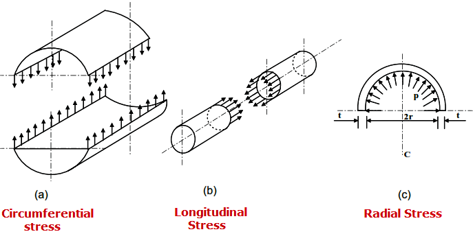
Circumferential Stress (Longitudinal Joints): When the thickness does not exceed one-half of the inside radius, or P does not exceed 0.385SE, the following formulas shall apply:
![]()
Longitudinal Stress (Circumferential Joints): When the thickness does not exceed one-half of the inside radius, or P does not exceed 1.25SE, the following formulas shall apply:
![]()
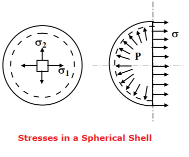
Spherical Shells: When the thickness of the shell of a wholly spherical vessel does not exceed 0.356R,or P does not exceed 0.665SE, the following formulas shall apply:
![]()
Where:
- E = joint efficiency for, or the efficiency of, appropriate joint in cylindrical or spherical shells, or the efficiency of ligaments between openings, whichever is less. For welded vessels, use the efficiency specified in UW-12. For ligaments between openings, use the efficiency calculated by the rules given in UG-53.
- P = internal design pressure (see UG-21)
- R =inside radius of the shell course under consideration,
- S = maximum allowable stress value (see UG-23 and the stress limitations specified in UG-24)
- t = minimum required thickness of shell
UG-28: THICKNESS OF SHELL UNDER EXTERNAL PRESSURE:
For further details, refer code.
UG-29: STIFFINING RINGS FOR CYLINDRICAL SHELLS UNDER EXTERNAL PRESSURE
The available moment of inertia of a circumferential stiffening ring shall be not less than that determined by one of the following two formulas;
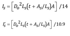
Where:
I = available moment of inertia of the stiffening ring cross section about its neutral axis parallel to the axis of the shell
Is= required moment of inertia of the stiffening ring cross section about its neutral axis parallel to the axis of the shell
I’ = available moment of inertia of combined ring-shell cross section about its neutral axis parallel to the axis of the shell.
I’s= required moment of inertia of the combined ring- shell cross section about its neutral axis parallel to the axis of the shell.
UG-30: ATTACHMENT OF STIFFINING RING
Refer code for details
UG-31: TUBES AND PIPES WHEN USED AS TUBES OR SHELLS
Refer UG-27 and additionally the thickness as determined in UG-27 shall be increased when necessary to meet the following requirements:
(1) Additional wall thickness should be provided when corrosion, erosion, or wear due to cleaning operations is expected.
(2) Where ends are threaded, additional wall thickness is to be provided in the amount of (20/n mm) [Where n equals the number of threads per 25.4 mm]
UG-32: FORMED HEADS, AND SECTIONS, PRESSURE ON CONCAVE SIDE
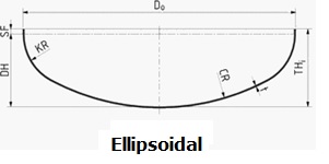
Ellipsoidal Heads with ts/L ≥ 0.002: The required thickness of a dished head of semi ellipsoidal form, in which half the minor axis (inside depth of the head minus the skirt) equals one-fourth of the inside diameter of the head skirt, shall be determined by;
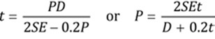
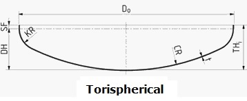
Torispherical Heads with ts/L ≥ 0.002: The required thickness of a tori spherical head for the case in which the knuckle radius is 6% of the inside crown radius and the inside crown radius equals the outside diameter of the skirt shall be determined by;
![]()
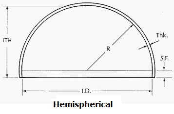
Hemispherical Heads: When the thickness of a hemispherical head does not exceed 0.356L, or P does not exceed 0.665SE, the following formulas shall apply;
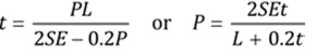
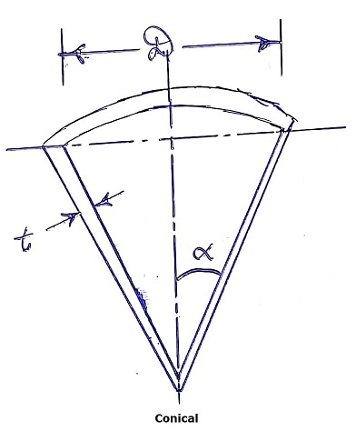
Conical Heads and Sections (Without Transition Knuckle): The required thickness of conical heads or conical shell sections that have a half apex-angle a not greater than 30 deg shall be determined by;
![]()
Where,
D = inside diameter of the head skirt; or inside length of the major axis of an ellipsoidal head; or inside diameter of a conical head at the point under consideration,
Measured perpendicular to the longitudinal axis
Di = inside diameter of the conical portion of a tori conical head at its point of tangency to the knuckle, measured perpendicular to the axis of the cone = D – 2r (1 – cos a)
E = lowest efficiency of any joint in the head; for hemispherical heads this includes head-to-shell joint; for welded vessels, use the efficiency specified in UW-12
L = inside spherical or crown radius. The value of L for ellipsoidal heads shall be obtained from Table UG-37.
P = internal design pressure (see UG-21)
r = inside knuckle radius
S = maximum allowable stress value in tension as given in the tables referenced in UG-23, except as limited in UG-24 and (d) below.
t = minimum required thickness of head after forming
ts= minimum specified thickness of head after forming. (mm). ts shall be > = t
a = one-half of the included (apex) angle of the cone at the centerline of the head
UG-33: FORMED HEADS, AND SECTIONS, PRESSURE ON CONVEX SIDE
Refer code for details.
UG-34: UNSTAYED FLAT HEAD AND COVERS
Refer code for details.
UG-35: OTHER TYPES OF CLOSURES:
The names will be mentioned only, these are
- UG -35.1 Dished Covers
- UG-35.2 Quick -Actuating closures
- UG35.3 Quick-Opening closures
Please click here to read the next part of this article.
(Note: Purpose of this article is to give a general guideline to the readers and it shall not be considered as a substitute of code. For full terms and conditions please read ASME Section VIII DIV I, 2017 edition)
This article is written and published by;
MR. SANDEEP SINGH PARMAR
(Ex. GE, ISGEC & ESSAR)
Email: sandeepparmar99@yahoo.com
IWE (IN/IWE/41700026); B Tech (Mechanical); AMIIW (Welding Technology)
ISO 9001:2008 Internal Auditor; ISO 9001:2015 Lead Auditor ;
NDE L-II (UT, LPT, MPI, RT); Lean Six Sigma Green Belt;
MWeldl IEng; MIE C Eng(Ind) ; M.I.Inst.W ; LM IIM