
Summary of ASME BPVC Section VIII Div 1 (Part 3)
In Part-2 of this article, the Subsection A was covered from UG-17 up to UG-35 Design and to read the Part-2 of this article please click here.
This article will deal with the general requirements preceding from UG-36 onwards.
Also note that the design calculation won’t be dealt within details and the readers are advised to refer the code for their specific type of vessel design.
To read the Interpretations of ASME Codes, Please click here.
Shape of opening: It can be cylindrical or conical in shells and be elliptical, circular or obround in heads.
Note: when the opening is other than as mentioned above the part of the vessel shall be subjected to a proof hydrostatic test in order to ascertain the safety of the pressure vessel.
Size of the opening:
- For vessels 1520 mm inside diameter and less, one- half the vessel diameter, but not to exceed 510 mm;
- For vessels over 1520 mm inside diameter, one-third the vessel diameter, but not to exceed 1020 mm.
- For an opening in an end closure, which is larger than one-half the inside diameter of the shell, one of the following alternatives to reinforcement may also be used:

Strength and design of finished opening: Will discuss the matter related to welding only;
- Welded, brazed, and flued connections meeting the applicable rules and with a finished opening not larger than: 89 mm diameter —in vessel shells or heads with a required minimum thickness of 10 mm or less;
- 60 mm diameter —in vessel shells or heads over a required minimum thickness of 10 mm;
- Openings through Welded Joints. Additional provisions governing openings through welded joints are given in UW-14.
As an opening (nozzle, manway etc.) is cut in pressure equipment’s the load normally carried out by the metal removed must be carried out by the wall adjacent to the opening this added load (of the material removed) increases the stress adjacent to the opening and hence excess thickness (in shell/ nozzle) needs to be provided in form of reinforcement to carry the additional load.
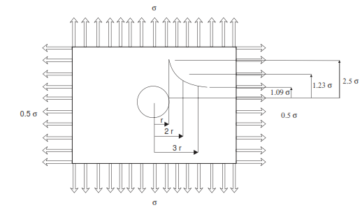
Figure shows stress distribution in a plate with circular opening. From above figure it is clear that the stress at the edge of the circular hole is 2.5 times the design stress and hence the area (in circumference) require reinforcement to avoid failure. For detailed calculation refer code.
UG- 38: FLUED OPENING IN SHELLS & FORMED HEADS
The minimum depth of flange exceeding 150 mm in any inside dimension, when not stayed by an attached pipe or flue, shall equal 3tr or tr+ 75 mm, whichever is less, where tr is the required shell or head thickness.
There is no minimum depth of flange requirement for flued out openings. For others openings refer code.
UG-39: REINFORCEMENT REQUIRED FOR OPENINGS IN FLAT HEADS
Single opening: When the opening does not exceed 0.5 times the Head dia, the total cross sectional area of reinforcement required in the plane under consideration shall be determined from below formulae:
![]()
Where;
- d= finished dia/dimensions
- t= specified vessel wall thickness
- tn= nozzle wall thickness
- fr1= allowable stress in nozzle/allowable stress in vessel
Multiple openings: With dia equal to or less than 0.5 times the head diameter, and no pair with an average dia greater than 0.25 times the head dia may be reinforced as a single opening using the above mentioned formulae.
When spacing between any pair of openings is less than 2 times but equal to or greater than 1.25 times the average diameter of the pair, the required reinforcement for each opening in the pair, as determined by above, shall be summed together and then distributed such that half of the sum is located between the two openings.
Spacing’s of less than 1.25 times the average diameter of adjacent openings shall be treated by rules of U-2(g).
For other types refer code.
UG-40: LIMITS OF REINFORCEMENT
The limits of reinforcement, measured parallel to the vessel wall, shall be at a distance, on each side of the axis of the opening, equal to the greater of the following:
- D (Dia of finished opening).
- Ri (inside radius) + tv (vessel thk)+ tn (nozzle thk).
The limits of reinforcement, measured normal to the vessel wall, shall conform to the contour of the surface at a distance from each surface equal to the smaller of the following:
- 2.5*tv (vessel thk).
- 2.5*tn (nozzle thk) + te(as per UG-40).
- For other details refer code.
UG-41: STRENGTH OF REINFORCEMENT
- Refer code for details
UG-42: REINFORCEMENT OF MULTIPLE OPENING
- Refer code for details
UG-43: METHODS OF ATTACHMENT OF PIPE AND NOZZLE NECKS TO VESSEL WALLS
- They can be welded, brazed, studded, threaded, expanded
UG-44: FLANGE AND PIPE FITTINGS
- Various standards are ASME B 16.1, ASME B 16.5, ASME B 16.9, ASME B 16.11, ASME B 16.15, ASME B 16.20, ASME B 16.24, ASME B 16.42, and ASME B 16.47.
- For other details refer code.
UG-45: NOZZLE NECK THICKNESS
- For access opening
![]()
- For other nozzles
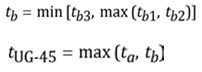
Where;
- tUG-45= minimum wall thickness of nozzle necks
- ta= minimum neck thickness required for internal & external pressure
- tb1= minimum neck thickness required for internal pressure (+ Corrosion allowance)
- tb2= minimum neck thickness required for external pressure (+ Corrosion allowance)
- tb3= thickness given in below table (+Corrosion allowance)
Nozzle minimum thickness requirements:
| Sr No. | Nominal Size | Minimum Wall Thickness (mm) |
| 1. | DN 6 | 1.51 |
| 2. | DN 8 | 1.96 |
| 3. | DN 10 | 2.02 |
| 4. | DN 15 | 2.42 |
| 5. | DN 20 | 2.51 |
| 6. | DN 25 | 2.96 |
| 7. | DN 32 | 3.12 |
| 8. | DN 40 | 3.22 |
| 9. | DN 50 | 3.42 |
| 10. | DN 65 | 4.52 |
| 11. | DN 80 | 4.80 |
| 12. | DN 90 | 5.02 |
| 13. | DN 100 | 5.27 |
| 14. | DN 125 | 5.73 |
| 15. | DN 150 | 6.22 |
| 16. | DN 200 | 7.16 |
| 17. | DN 250 | 8.11 |
| 18. | DN 300 | 8.34 |
UG-46: INSPECTION OPENINGS
- For further details, refer code.
UG-47: BRACED AND STRAYED SURFACES
- For Further details, refer code
UG-48-49-50: STAY BOLTS, ITS LOCATION & ITS DIMENSIONS
- Refer code for details
UG-53: LIGAMENTS
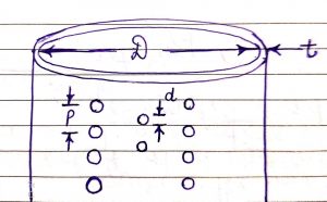
- Pitch of tube holes in every row equal use below formulae;

- Pitch of tube holes in one of the row is unequal use below formulae;

Where;
- d= dia of tube holes
- n= no of pitch holes in length p1
- p= longitudinal pitch of the tube holes
- p1= unit length of ligament
Refer code for other details.
UG-54-55: SUPPORTS, LUGS FOR PLATFORMS, LADDERS AND OTHER ATTACHMENTS TO VESSEL WALLS
- Refer code for details
UG-75: GENERAL FABRICATION
- The exact necessities of ULW-75 agreed in the appropriate parts of subsection B and C shall be met.
UG-76: CUTTING PLATES & OTHER STOCKS
- For cutting of plates & other stocks machining, shearing, grinding, oxygen or arc cutting can be used.
- All Slag and discoloration formed on surface by above means to be removed before fabrication.
- Inside edges shall be rounded/chamfered.
UG-77: MATERIAL IDENTIFICATION
- Original marking on parts, traceability of parts to the original marking shall be maintained by the vessel manufacturer by suitable means.
- Transfer of marking shall be before cutting and may or may not be witnessed by the inspector.

- For other details refer code.
UG-78: REPAIR OF DEFECTS IN MATERIALS
- Inspector concurrence shall be obtained beforehand.
UG-79: FORMING PRESSURE PARTS
- Limits of cold working are given in UCS-79(d), UNF-79(a), UHA-44(a), and UHT-79 (a) for various materials.
- In order to avoid flat spots along the completed joints in a cylindrical shell proper rolling or forming shall be performed before fabrication.
- When parts of vessel are cold formed by vendors, the certification for the part shall mention weather or not the part was heat treated.
- The following conditions shall be met for accepting reduction in part thickness due to forming:
- Inspector check the part compliance from UW-35(a) thru UW-35(d) prior to forming.
- Forming shall not reduce the part thickness below design requirements.
- Max Reduction =1mm or 10% of nominal thk of adjoining surface, whichever is less.
| Table UG-79-1 Equations for Calculating Forming Strains | ||
| Sr No | Type of Part Being Formed | Forming Strains |
| 1. | Cylinders formed from plate | Ƹf =(50*t/Rf)*(1-Rf/R0) |
| 2. | For double curvature (eg, heads) | Ƹf =(75*t/Rf)*( 1-Rf/R0) |
| 3. | Tube and pipe bends | Ƹf =100*r/R |
Where;
- Ƹf = extreme fiber elongation
- Rf= final mean radius
- R0= original mean radius
- R= nominal bending radius to centerline of pipe
(Note: Purpose of this article is to give a general guideline to the readers and it shall not be considered as a substitute of code. For full terms and conditions please read ASME Section VIII DIV I, 2017 edition).
This article is written and published by;
MR. SANDEEP SINGH PARMAR
(Ex. GE, ISGEC & ESSAR)
Email: sandeepparmar99@yahoo.com
IWE (IN/IWE/41700026); B Tech (Mechanical); AMIIW (Welding Technology)
ISO 9001:2008 Internal Auditor; ISO 9001:2015 Lead Auditor ;
NDE L-II (UT, LPT, MPI, RT); Lean Six Sigma Green Belt;
MWeldl IEng; MIE C Eng(Ind) ; M.I.Inst.W ; LM IIM


Dear sir,
Please explain more PQR, WPS and WPQ to understand and clear concepts of welding documents.Also explain couples of tube to tubesheet mockup qualifications.
Sir can you please send Formula and explain difference between skipdistance and surface distance. And how to find depth of defect.